|
10-7 VPN
網路規劃與管理
內容:
10-7-1 VPN
網路規劃
(請匯入:VPN
網路_空白.pkt)
目前公司有兩個重要據點:高雄總公司與紐約分公司,兩公司內大約都有
100
部工作站。公司期望將兩地的網路透過網際網路結合一個虛擬私有網路,期望網路架構圖,如圖 10-28
所示。
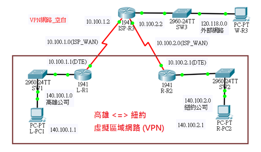
圖 10-28
VPN
網路範例規劃
(A)
網路概況
VPN
網路架構可區分為:本地網路、遠端網路與 ISP
網路等三大部分,VPN
兩網路透過廣域網路
(WAN) 的
Serial 連線銜接到
ISP 網路,兩地封包是透過
ISP 轉送到達目的地。網路架構說明如下:
█
高雄私有網路(140.100.1.0/24):由
Cisco 1941(L-R1) 路由器建置而成,由
L-PC1 主機(192.168.0.1)
代表本地主機。
█
紐約私有網路(140.100.2.0/24):由
Cisco 1941 路由器建置而成,由
R-PC2 (192.168.100.1)
主機代表遠端主機。
█
ISP
公眾網路:由
Cisco 1941 路由器代表,並連接外部網路
(120.118.0.0/24),並以
W-R3 (120.118.0.1) 主機代表。
(B)
網路規劃與建置
█
網路環境規劃
|
網路區段 |
Gateway/DNS |
名稱 |
IP
位址 |
連結介面 |
|
140.100.1.0
255.255.255.0 |
140.100.1.254
168.95.1.1 |
L-PC1 |
140.100.1.1/24 |
SW1(Fa0/1) |
|
140.100.2.0
255.255.255.0 |
140.100.2.254
168.95.1.1 |
R-PC2 |
140.100.2.1/24 |
SW2(Fa0/1) |
|
120.118.0.0
255.255.255.0 |
120.118.0.1
168.95.1.1 |
W-PC3 |
120.118.0.1/24 |
SW3(Fa0/1) |
|
10.100.1.0
255.255.255.0 |
|
ISP-WAN |
|
|
|
10.100.2.0
255.255.255.0 |
|
ISP-WAN |
|
|
█
路由器規劃:
|
路由器 |
網路區段 |
IP
位址 |
埠口 |
對應埠口 |
|
L-R1 |
140.100.1.0/24 |
140.100.1.254 |
Gi0/0 |
Gi0/1(SW1) |
|
10.100.1.0/24 |
10.100.1.1(DTE) |
Se0/1/0 |
Se0/1/0(ISP-R3) |
|
R-R2 |
140.100.2.0/24 |
140.100.2.254 |
Gi0/0 |
Gi0/0(SW2) |
|
10.100.2.0/24 |
10.100.2.1(DTE) |
Se0/1/0 |
Se0/1/1(ISP-R3) |
|
ISP-R3 |
10.100.1.0/24 |
10.100.1.2(DCE) |
Se0/1/0 |
Se0/1/0(L-R1) |
|
10.100.2.0/24 |
10.100.2.2(DCE) |
Se0/1/1 |
Se0/1/0(R-R2) |
|
120.118.0.0/24 |
120.118.0.254 |
Gi0/0 |
Gi0/1(SE3) |
█
ISP-WAN
網路連線規劃:
網路連線規劃:
|
網路 |
型態 |
介面 |
IP
位址 |
bandwidth |
Clock rate |
|
10.100.1.0/24 |
DCE |
ISP-R3(se0/1/0) |
10.100.1.2 |
10(1G) |
56000 |
|
DTE |
L-R1(se0/1/0) |
10.100.1.1 |
10 (1G) |
|
|
10.100.2.0/24 |
DCE |
ISP-R3(Se0/1/1) |
10.100.2.2 |
10 (1G) |
56000 |
|
DTE |
R-R2(Se0/1/0) |
10.100.2.1 |
10 (1G) |
|
█
靜態繞路規劃:
依照圖 10-13,盡量讓網路內各主機可繞路成功,規劃如下:
規劃如下:
|
Router |
Destination AD |
Network Mask |
Net Hop |
備註 |
|
L_R1 |
0.0.0.0 |
0.0.0.0 |
10.100.1.2 |
往外傳送 |
|
R_R2 |
0.0.0.0 |
0.0.0.0 |
10.100.2.2 |
往外傳送 |
|
ISP_R3 |
140.100.1.0 |
255.255.255.0 |
10.100.1.1 |
往內傳送 |
|
140.100.2.0 |
255.255.255.0 |
10.100.2.1 |
往內傳送 |
|
0.0.0.0 |
0.0.0.0 |
120.118.0.1 |
往外傳送 |
(C) L-R1
路由器網路設定
|
L-R1#config ter
L-R1(config)#int
gi0/0
L-R1(config-if)#ip
address 140.100.1.254 255.255.255.0
L-R1(config-if)#no
shutdown
L-R1(config-if)#int
s0/1/0
L-R1(config-if)#ip
address 10.100.1.1 255.255.255.0
L-R1(config-if)#bandwidth
10
L-R1(config-if)#no
shutdown
L-R1(config-if)#exit
L-R1(config)#ip route
0.0.0.0 0.0.0.0 10.100.1.2
L-R1(config)#do show
ip int brief
GigabitEthernet0/1 unassigned YES unset
administratively down down
Serial0/1/0 10.100.1.1 YES manual up up
Serial0/1/1 unassigned YES unset administratively
down down
Vlan1 unassigned YES unset administratively down down
L-R1(config)#do show
ip route
Gateway of last resort is 10.100.1.2 to network
0.0.0.0 |
(D) R-R2
路由器網路設定
|
R-R2>en
R-R2#config ter
R-R2(config)#int
gi0/0
R-R2(config-if)#ip
address 140.100.2.254 255.255.255.0
R-R2(config-if)#no
shutdown
R-R2(config-if)#int
s0/1/0
R-R2(config-if)#ip
address 10.100.2.1 255.255.255.0
R-R2(config-if)#bandwidth
10
R-R2(config-if)#no
shutdown
R-R2(config-if)#exit
R-R2(config)#ip route
0.0.0.0 0.0.0.0 10.100.2.2
R-R2(config)# |
(E) ISP-R3
路由器網路設定
|
ISP-R3#config ter
ISP-R3(config)#int
gi0/0
ISP-R3(config-if)#ip
address 120.118.0.254 255.255.255.0
ISP-R3(config-if)#no
shutdown
ISP-R3(config-if)#int
s0/1/0
ISP-R3(config-if)#ip
address 10.100.1.2 255.255.255.0
ISP-R3(config-if)#bandwidth
10
ISP-R3(config-if)#clock
rate 500000
ISP-R3(config-if)#no
shutdown
ISP-R3(config-if)#int
s0/1/1
ISP-R3(config-if)#ip
address 10.100.2.2 255.255.255.0
ISP-R3(config-if)#bandwidth
10
ISP-R3(config-if)#clock
rate 500000
ISP-R3(config-if)#no
shutdown
ISP-R3(config-if)#exit
ISP-R3(config)#ip
route 140.100.1.0 255.255.255.0 10.100.1.1
ISP-R3(config)#ip
route 140.100.2.0 255.255.255.0 10.100.2.1
ISP-R3(config)#ip
route 0.0.0.0 0.0.0.0 120.118.0.1
ISP-R3(config)#do
show ip route
Gateway of last resort is 120.118.0.1 to network
0.0.0.0
10.0.0.0/8 is variably subnetted, 4 subnets, 2 masks
C 10.100.1.0/24 is directly connected, Serial0/1/0
L 10.100.1.2/32 is directly connected, Serial0/1/0
C 10.100.2.0/24 is directly connected, Serial0/1/1
L 10.100.2.2/32 is directly connected, Serial0/1/1
120.0.0.0/8 is variably subnetted, 2 subnets, 2 masks
C 120.118.0.0/24 is directly connected,
GigabitEthernet0/0
L 120.118.0.254/32 is directly connected,
GigabitEthernet0/0
140.100.0.0/24 is subnetted, 2 subnets
S 140.100.1.0/24 [1/0] via 10.100.1.1
S 140.100.2.0/24 [1/0] via 10.100.2.1
S* 0.0.0.0/0 [1/0] via 120.118.0.1
ISP-R3(config)# |
(F)
網路繞路測試
(請匯入:VPN
網路_網路設定.pkt)
l
L-PC1 ping 140.100.2.1
l
L-PC1 ping 120.118.0.1
l
R-PC2 ping 140.100.1.1
l
W-R3 ping 140.100.2.1
10-7-2 ISAKMP
安全套件規劃
(A) ISAKMP Phase 1:協商參數
吾人依照
ISAKMP 與
IKE 協定,規劃安全套件如下表:
|
參數 |
L_R1 |
R_R2 |
|
鑰匙分配方法 |
Manual or ISAKMP |
ISAKMP |
ISAKMP |
|
加密演算法 |
DES、3DES、ASE |
AES |
AES |
|
雜湊演算法 |
MD5、SHA-1 |
SHA-1 |
SHA-1 |
|
認證方法 |
Pre-shared keys、RSA |
Pre-share |
Pre-share |
|
鑰匙交換 |
DH Group1、2、5 |
DH 2 |
DH 2 |
|
IKE Lifetime |
86400
Sec. or less |
86400 |
86400 |
|
ISAKMP Key |
(自行定義) |
csuMIS |
csuMIS |
(B) ISAKMP Phase 2:協商參數
吾人依照
ISAKMP 與
IKE 協定,規劃安全套件如下表:
|
參數 |
L_R1 |
R_R2 |
|
安全套件名稱
(自行定義) |
VPN-SET |
VPN-SET |
|
安全套件內容:IPSec
協定 |
ESP-AES、ESP-SHA-HMAC |
ESP-AES、ESP-SHA-HMAC |
|
對方主機 |
R_R2 |
L_R1 |
|
對方
IP 位址 |
10.100.1.1 |
10.100.2.1 |
|
加密網路範圍 |
140.100.1.0/24 |
140.100.2.0/24 |
|
網路範圍名稱
(自行定義) |
VPN-MAP |
VPN-MAP |
|
SA
建立方法 |
ipsec-isakmp |
ipsec-isakmp |
10-7-3 IPSec VPN
設定
接下來,我們設定
L-R1 與
R-R2 之間『位置對位置』(Sit-to-Sit)
之間的
IPSec VPN,使兩邊網路結合成一個區域網路,並保證之間傳送是經過安全保護著。但它們之間傳遞的封包也許會經過多個路由器轉送,本範例僅用
ISP-R3 取代,表示是經過
ISP 公眾網路並在沒有安全保護底下轉送。設定步驟如下:
█ 步驟
1:啟動
L_R1安全套件與規劃
IPSec 參數、
█
步驟
2:啟動
R_R2 安全套件與規劃
IPSec 參數、
█
步驟
3:驗證
IPSec VPN 功能。
(A)
L_R1
的
IPSec VPN
設定
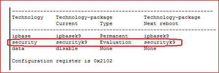
█ 啟動安全套件
『安全技術套件』(Security
Technology Package, STP)
授權需啟動,才能使用相關套件,操作如下:
|
L-R1>en
L-R1#show version
…… [套件授權模組
C1900,並還未啟動]
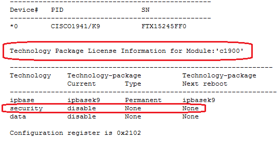
[起啟動命令如下]
L-R1#config ter
L-R1(config)#license
boot module c1900 technology-package securityk9
L-R1(config)#end
L-R1#copy running-config
startup-config
L-R1#reload
….
L-R1#show version
…….[顯示已啟動成功]
 |
█ 設定訊務範圍
- ACL
L-R1 的管制流量(Ineresting
Traffic) 即是他所銜接的網路
140.100.1.0/24 網路區段流向
R-R2 所管轄網路
140.100.2.0/24 之間的訊息。如果
R-R2 的管制流量即是相反方向。我們用
Access List 將它設定完成,如下:
|
L-R1(config)#ip
access-list extended VPN-Traffic
L-R1(config)# permit
ip 140.100.1.0 0.0.0.255 140.100.2.0 0.0.0.255 |
█ 設定
IKE Phase 1
參數
設定 Phase 1
相關參數如下:
|
L-R1(config)#crypto
isakmp policy 10 [安全編號
10]
L-R1(config-isakmp)#encryption
aes 256
L-R1(config-isakmp)#authentication
pre-share
L-R1(config-isakmp)#group
2 [DH Group 2
參數]
L-R1(config-isakmp)#lifetime
86400
L-R1(config-isakmp)#exit
L-R1(config)#crypto
isakmp key csuMIS address 10.100.2.1
L-R1(config)# |
█ 設定
IKE Phase 2
參數
首先設定安全套件名稱為『VPN-SET』,並選擇採用
esp-aes (ESP Cipher) 與
esp-sha-hmac (ESP 訊息認證演算法),並將設定的加入
Crypto Map (VPN-MAP)
密件套件內,再將它嵌入網路介面內 (Se0/1/0)
,如下:
如下:
|
L-R1(config)#crypto ipsec transform VPN-SET
esp-aes esp-sha-hmac
[安全套件名稱
VPNSET,以及
ESP-AES
密碼系統]
L-R1(config)#crypto map VPN-MAP 10
ipsec-isakmp
[建立範圍名稱
VPN-MAP,採安全標號
10與
isakmp方式溝通]
L-R1(config-crypto-map)#set peer
10.100.2.1
L-R1(config-crypto-map)#set transform-set
VPN-SET
L-R1(config-crypto-map)#match address VPN-Traffic
L-R1(config-crypto-map)#exit
L-R1(config)#int se0/1/0
L-R1(config-if)#crypto map VPN-MAP
*Jan 3 07:16:26.785: %CRYPTO-6-ISAKMP_ON_OFF: ISAKMP
is ON
L-R1(config-if)# |
(B)
R_R2
的
IPSec VPN
設定
(大致上與
L-R1
相同)
█ 啟動安全套件
『安全技術套件』(Security
Technology Package, STP)
授權需啟動,才能使用相關套件,操作如下:
|
R-R2>en
R-R2#show version
…… [套件授權模組
C1900,並還未啟動]

[如果還未啟動,起啟動命令如下]
R-R2(config)#license
boot module c1900 technology-package securityk9
R-R2(config)#exit
R-R2#copy running-config
startup-config
R-R2#reload
….
R-R2#show version
…….[顯示已啟動成功]
 |
█ 設定管制流量
- ACL
L-R1 的管制流量(Ineresting
Traffic) 即是他所銜接的網路
140.100.1.0/24 網路區段流向
R-R2 所管轄網路
140.100.2.0/24 之間的訊息。如果
R-R2 的管制流量即是相反方向。我們用
Access List 將它設定完成,如下:
|
R-R2(config)#ip
access-list extended VPN-Traffic
R-R2(config-ext-nacl)#permit
ip 140.100.2.0 0.0.0.255 140.100.1.0 0.0.0.255
R-R2(config-ext-nacl)#exit |
█ 設定
IKE Phase 1
參數
設定 Phase 1
相關參數如下:
|
R-R2(config)#crypto
isakmp policy 10
R-R2(config-isakmp)#encryption
aes 256
R-R2(config-isakmp)#authentication
pre-share
R-R2(config-isakmp)#group
2
R-R2(config-isakmp)#lifetime
86400
R-R2(config-isakmp)#exit
R-R2(config)#crypto
isakmp key csuMIS address 10.100.1.1 |
█ 設定
IKE Phase 2
參數
首先設定安全套件名稱為『VPN-SET』,並選擇採用
esp-aes (ESP Cipher) 與
esp-sha-hmac (ESP 訊息認證演算法),並將設定的加入
Crypto Map (VPN-MAP)
密件套件內,再將它嵌入網路介面內 (Se0/1/0)
,如下:
|
R-R2(config)#crypto
isakmp key csuMIS address 10.100.1.1
R-R2(config)#crypto
ipsec transform VPN-SET esp-aes esp-sha-hmac
R-R2(config)#crypto
map VPN-MAP 10 ipsec-isakmp
%
NOTE: This new crypto map will remain disabled until a peer
and
a valid access list have been configured.
R-R2(config-crypto-map)#set
peer 10.100.1.1
R-R2(config-crypto-map)#set
transform-set VPN-SET
R-R2(config-crypto-map)#match
address VPN-Traffic
R-R2(config-crypto-map)#exit
R-R2(config)#int
s0/1/0
R-R2(config-if)#crypto
map VPN-MAP
*Jan 3 07:16:26.785: %CRYPTO-6-ISAKMP_ON_OFF: ISAKMP
is ON
|
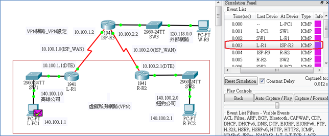
(C)
驗證通訊連線
:(請匯入:VPN
網路_VPN設定.pkt)
█
L-PC1 (140.100.1.1)
測試:
> ping 140.100.2.1 (R-PC2)
[OK]
> ping 120.118.0.1 (W-R3) [OK]
█
R-PC2 (140.100.2.1)
測試:
> ping 140.100.1.1 (L-PC1)
[OK]
> ping 120.118.0.1 (W-R3)
[OK]
█
R-R3 (120.118.0.1)
測試:
> ping 140.100.2.1 (R-PC2)
[OK]
> ping 140.100.1.1 (L-PC1)
[OK]
10-7-4
IPSec VPN
傳輸驗證
(請匯入:VPN
網路_VPN設定.pkt)
(A)
觀察產生
IPSec SA(安全關聯)
█
步驟
1:於
L-R1 上觀察
ipsec sa
|
L-R1#show crypto
ipsec sa
interface: Serial0/1/0
Crypto map tag: VPN-MAP, local addr 10.100.1.1
protected vrf: (none)
local ident (addr/mask/prot/port):
(140.100.1.0/255.255.255.0/0/0)
remote ident (addr/mask/prot/port):
(140.100.2.0/255.255.255.0/0/0)
current_peer 10.100.2.1 port 500
PERMIT, flags={origin_is_acl,}
#pkts encaps: 0, #pkts
encrypt: 0, #pkts digest: 0
#pkts decaps: 0, #pkts
decrypt: 0, #pkts verify: 0
#pkts compressed: 0, #pkts
decompressed: 0
#pkts not compressed: 0, #pkts
compr. failed: 0
#pkts not decompressed: 0,
#pkts decompress failed: 0
#send errors 0, #recv
errors 0
… |
█
步驟
2:於
L-PC1 ping R-PC2
讓
SA 產生動作
|
C:\>ping 140.100.2.1
[OK] |
█
步驟
3:再觀察
L-R1 的
ipsec sa
|
L-R1#show crypto
ipsec sa
interface: Serial0/1/0
Crypto map tag: VPN-MAP, local addr 10.100.1.1
protected vrf: (none)
local ident (addr/mask/prot/port):
(140.100.1.0/255.255.255.0/0/0)
remote ident (addr/mask/prot/port):
(140.100.2.0/255.255.255.0/0/0)
current_peer 10.100.2.1 port 500
PERMIT, flags={origin_is_acl,}
#pkts encaps: 3, #pkts
encrypt: 3, #pkts digest: 0 [已產生
IPSec 封包]
#pkts decaps: 2, #pkts
decrypt: 2, #pkts verify: 0
#pkts compressed: 0, #pkts decompressed: 0
#pkts not compressed: 0, #pkts compr. failed: 0
#pkts not decompressed: 0, #pkts decompress failed: 0
#send errors 1, #recv errors 0
local crypto endpt.: 10.100.1.1, remote crypto endpt.:10.100.2.1
path mtu 1500, ip mtu 1500, ip mtu idb Serial0/1/0
current outbound spi: 0x11E25D0F(300047631) |
(B)
觀察
IPSec SA
相關設定
(由
L-R1
操作)
█
查詢
IPSec Transform-set
|
L-R1#show crypto
ipsec transform-set
Transform set VPN-SET: { { esp-aes esp-sha-hmac }
will negotiate = { Tunnel, },
Transform set #$!default_transform_set_1: { esp-aes
esp-sha-hmac }
will negotiate = { Transport, },
Transform set #$!default_transform_set_0: { esp-3des
esp-sha-hmac }
will negotiate = { Transport, }, |
█
查詢
isakmp sa
|
L-R1#show crypto
isakmp sa
IPv4 Crypto ISAKMP SA
dst src state conn-id slot
status
10.100.2.1 10.100.1.1 QM_IDLE 1019 0
ACTIVE |
█
查詢
isakmp policy
|
L-R1#show crypto
isakmp policy
Global IKE policy
Protection suite of priority 10
encryption algorithm: AES - Advanced Encryption
Standard (256 bit keys).
hash algorithm: Secure Hash Standard
authentication method: Pre-Shared Key
Diffie-Hellman group: #2 (1024 bit)
lifetime: 86400 seconds, no volume limit |
█
查詢
crypto map
|
L-R1#show crypto map
Crypto Map VPN-MAP 10 ipsec-isakmp
Peer = 10.100.2.1
Extended IP access list VPN-Traffic
access-list VPN-Traffic permit ip 140.100.1.0
0.0.0.255 140.100.2.0 0.0.0.255
Current peer: 10.100.2.1
Security association lifetime: 4608000 kilobytes/3600
seconds
PFS (Y/N): N
Transform sets={
VPN-SET,
}
Interfaces using crypto map VPN-MAP:
Serial0/1/0 |
(C)
觀察
IPSec
封包內的
ESP
標頭
█
由
L-PC1 ping R-PC2:
將 Packet
Tracer 設定成
Simulation Mode,再由
L-PC1 ping R-PC2,觀察封包進出
L-R1 路由器之前與之後之封包,如下:
█
擷取進入
L-R1 之前的
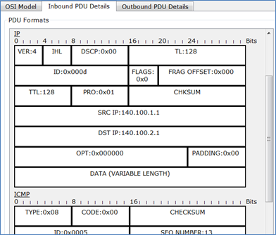
IP 封包
封包沒有經過
IPSec ESP 包裝的原始
IP 封包。
█
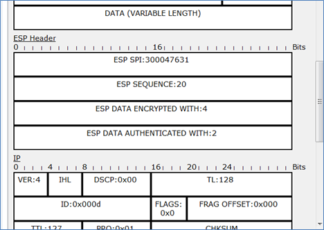
擷取離開
L-R1之後的
IP 封包
IP 封包經過
IPSec ESP 包裝後型態。
(D)
觀察
ISAKMP
封包協定運作
█
請自行練習
|

翻轉工作室:粘添壽
網路規劃與管理技術:
翻轉電子書系列:
|