|
8-4
多交換器 VLAN
網路
內容:
8-4-1
多交換器網路規劃
(A)
系統分析
(請匯入:多交換器
VLAN 網路_空白.pkt)
我們利用三個交換器來建立一套多交換器的
VLAN 網路,再來驗證
VTP 與
Trunk
建立的方法,期望網路架構圖 8-10
所示。
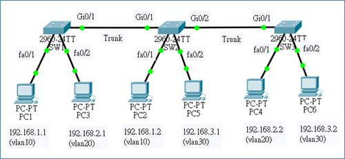
圖 8-11
三只交換器建立
VLAN
網路
(B)
網路規劃與建置
(1)
設備:Cisco
2960 交換器三台(SW1
~ SW3)、個人電腦
6 台
(PC1 ~ PC6)。
(2)
VLAN 網路環境:
|
VLAN |
網路區段 |
Gateway/DNS |
IP (PC) |
埠口(Switch) |
|
Vlan10
(Sales) |
192.168.1.0/24 |
192.168.1.254/
168.95.1.1 |
PC1=192.168.1.1 |
Fa0/1 (SW1) |
|
PC2=192.168.1.2 |
Fa0/1(SW2) |
|
Vlan20
(managers) |
192.168.2.0/24 |
192,168.2.254/
168.95.1.1 |
PC3=192.168.2.1 |
Fa0/2(SW1) |
|
PC4=192.168.2.2 |
Fa0/1(SW3) |
|
Vlan30
(Products) |
192.168.3.0/24 |
192.168.3.254/
168.95.1.1 |
PC5=192.168.3.1 |
Fa0/2(SW2) |
|
PC6=192.168.3.2 |
Fa0/2(SW3) |
(3)
VTP Domain 規劃:
|
Switch no |
VTP Mode |
Trunk port |
|
SW1 |
Server |
Gi0/1=>Gi0/1(SW2) |
|
SW2 |
Client |
Gi0/1 => Gi0/1(SW1)
Gi0/2 => Gi0/1(SW3) |
8-4-2
多交換器
VLAN
網路設定
(A)
在SW1
交換器需設定下列參數:
(1)
設定為
VTP server mode、VTP
Domain = CSU_MIS(password=user)。
(2)
建立
VLAN 10、VLAN
20、VLAN
30 虛擬區域網路。
(3)
設定介面
Gi0/1 為
switchport mode trunk。
(4)
將
Fa0/1 加入
vlan10、Fa0/2
加入
vlan20。
|
##
設定
VTP
操作模式 ###
SW1>
SW1>en
SW1#config ter
SW1(config)#vtp mode
server
SW1(config)#vtp domain
CSU_MIS
SW1(config)#vtp
password user
SW1(config)#do show
vtp status
VTP Version : 2
Configuration Revision : 0
Maximum VLANs supported locally : 255
Number of existing VLANs : 5
VTP Operating Mode : Server
VTP Domain Name : CSU_MIS
VTP Pruning Mode : Disabled
VTP V2 Mode : Disabled
VTP Traps Generation : Disabled
….
SW1(config)#do show
vtp password
VTP Password: user
SW1(config)#
##
建立
VLAN id
與
name ###
SW1(config)#vlan 10
SW1(config-vlan)#name
Sales
SW1(config-vlan)#exit
SW1(config)#vlan 20
SW1(config-vlan)#name
Managers
SW1(config-vlan)#exit
SW1(config)#vlan 30
SW1(config-vlan)#name
Product
SW1(config-vlan)#exit
SW1(config)#do show
vlan brief
…
10 Sales active
20 Managers active
30 Products active
##
設定
VLAN trunk
傳輸骨幹
###
SW1(config)#int gi0/1
SW1(config-if)#switchport
mode trunk
##
設定
VLAN
網路成員的介面埠口 ###
SW1(config-if)#exit
SW1(config)#int fa0/1
SW1(config-if)#switchport
access vlan 10
SW1(config-if)#exit
SW1(config)#int fa0/2
SW1(config-if)#switchport
access vlan 20
SW1(config-if)#exit
##
觀察各
VLAN
網路的成員 ###
SW1(config)#do show
vlan brief
…
10 Sales active Fa0/1
20 Managers active Fa0/2
30 Products active
…
##
儲存設定結果
###
SW1#copy running-config
startup-config |
(B)
在SW2
交換器需設定下列參數:
(1)
設定為
VTP mode client、VTP
Domain = CSU_MIS(password=user)
(2)
設定介面
Gi0/1 與
Gi0/2 為
switchport mode trunk。
(3)
將 Fa0/1
加入
vlan10、Fa0/2
加入
vlan30。
|
##
設定
VTP
操作模式與環境 ###
SW2>en
SW2#config ter
SW2(config)#vtp mode
client
SW2(config)#vtp domain
CSU_MIS
SW2(config)#vtp
password user
SW2(config)#do show
vtp status
…
VTP Operating Mode : Client
VTP Domain Name : CSU_MIS
VTP Pruning Mode : Disabled
VTP V2 Mode : Disabled
…
#####
設定
VLAN
主幹 trunk
埠口
#####
SW2(config)#int gi0/1
SW2(config-if)#switchport
mode trunk
SW2(config-if)#no
shutdown
SW2(config-if)#exit
SW2(config)#int gi0/2
SW2(config-if)#switchport
mode trunk
#####
設定
VLAN
埠口 #####
witch(config-if)#exit
SW2(config)#int fa0/1
SW2(config-if)#switchport
access vlan 10
SW2(config-if)#exit
SW2(config)#int fa0/2
SW2(config-if)#switchport
access vlan 30
SW2(config-if)#exit
#####
顯示各
VLAN
的成員埠口 #####
SW2(config)#do show
vlan brief
…
10 Sales active Fa0/1
20 Managers active
30 Products active Fa0/2
…
##
儲存設定結果
###
SW2#copy running-config
startup-config |
(C)
在SW3
交換器需設定下列參數:
(1)
設定為 VTP
mode client、VTP
Domain = CSU_MIS(password=user)
(2)
設定介面
Gi0/1 為
switchport mode trunk。
(3)
將
Fa0/1 加入
vlan20、Fa0/2
加入
vlan30。
|
#####
設定
VTP
操作模式與環境 ####
SW3>en
SW3#config ter
SW3(config)#vtp mode
client
SW3(config)#vtp domain
CSU_MIS
SW3(config)#vtp
password user
SW3(config)#do show
vtp status
...
VTP Operating Mode : Client
VTP Domain Name : CSU_MIS
VTP Pruning Mode : Disabled
…
#####
設定
VLAN
主幹埠口 #####
SW3(config)#int gi0/1
SW3(config-if)#switchport
mode trunk
#####
設定
VLAN
埠口 #####
SW3(config-if)#exit
SW3(config)#int fa0/1
SW3(config-if)#switchport
access vlan 20
SW3(config-if)#exit
SW3(config)#int fa0/2
SW3(config-if)#switchport
access vlan 30
SW3(config-if)#exit
#####
顯示各
VLAN
的成員埠口 #####
SW3(config)#do show
vlan brief
….
10 Sales active
20 Managers active Fa0/1
30 Products active Fa0/2
….
##
儲存設定結果
###
SW3#copy running-config startup-config
|
(D)
測試連線成果
(請匯入:多交換器網路_VLAN
設定.pkt)
(1)
步驟
1:同一個
VLAN 網路(但跨越不同交換器)內是否可以連線。由
PC1 ping PC2,如下:(分別在
PC1、PC3、PC3主機下操作)
l
於
PC1 下操作,ping
PC2(192.168.1.2) 測試
VLAN 10 連線:
|
C:\>ping
192.168.1.2 [OK] |
l
於
PC3 下操作,ping
PC4(192.168.2.2) 測試
VLAN 20 連線:
|
C:\>ping
192.168.2.2 [OK] |
l
於
PC5 下操作,ping
PC6(192.168.3.2) 測試
VLAN 30 連線:
|
C:\>ping
192.168.3.2 [OK] |
(2)
步驟
2:不同
VLAN 網路之間是否可以連線。由
PC1 ping PC3 與由
PC1 ping PC6,如下:(在
PC1 主機下操作,ping
PC3,同一交換器但不同
VLAN 網路)
|
C:\>ping
192.168.2.1 [連線不成功,表示沒經過路由器轉接無法成功]
C:\>ping
192.168.3.1 [連線不成功] |
8-4-3
多交換器
VLAN
繞路設定
(A)
系統分析
(請匯入:多交換器網路_VLAN
設定+繞路_空白.pkt)
我們延伸圖 8-10
將使用具有繞路的功能,如圖
8-11
所示。我們增加了一個具有三個埠口的路由器,每一埠口負責一個 VLAN
的通道,並設定該
VLAN 的預設路由。
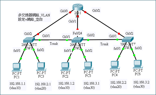
圖 8-12
具繞路功能的
VLAN
網路
(B)
網路規劃與建置
(1)
設備:Cisco
2960 交換器三台(SW1
~ SW3)、個人電腦
6 台
(PC1 ~ PC6)。
(2)
路由器:Cisco
2911 一台,內建有
3 只
Gigabit Ethernet 卡,每只網路卡當作一個
VLAN 網路的預設路由。
(3)
網路環境:(與圖
8-10 相同不用變更)
與圖
8-10 相同不用變更)
|
VLAN |
網路區段 |
Gateway/DNS |
IP (PC) |
埠口(Switch) |
|
Vlan10
(Sales) |
192.168.1.0/24 |
192.168.1.254/
168.95.1.1 |
PC1=192.168.1.1 |
Fa0/1 (SW1) |
|
PC2=192.168.1.2 |
Fa0/1(SW2) |
|
R1(Gi0/0)=192.168.1.254 |
Gi0/2(SW1) |
|
Vlan20
(managers) |
192.168.2.0/24 |
192,168.2.254/
168.95.1.1 |
PC3=192.168.2.1 |
Fa0/2(SW1) |
|
PC4=192.168.2.2 |
Fa0/1(SW3) |
|
R1(Gi0/1)=192.168.2.254 |
Fa0/24(SW2) |
|
Vlan30
(Products) |
192.168.3.0/24 |
192.168.3.254/
168.95.1.1 |
PC5=192.168.3.1 |
Fa0/2(SW2) |
|
PC6=192.168.3.2 |
Fa0/2(SW3) |
|
R1(Gi0/2)=192.168.3.254 |
Gi0/2(SW3) |
(4)
交換機環境規劃:
|
Switch no |
VTP Mode |
Trunk port |
|
SW1 |
Server |
Gi0/1=>Gi0/1(SW2) |
|
SW2 |
Client |
Gi0/1 => Gi0/1(SW1)
Gi0/2 => Gi0/1(SW3) |
|
SW3 |
Client |
Gi0/1 => Gi02(SW2) |
|
VTP Domain = CSU_MIS、Password
= user |
(5)
路由器環境規劃:(新增)
|
Router |
Router port |
IP
位址 |
VLAN |
Switch port |
|
R1 |
Gi0/0 |
192.168.1.254 |
10 |
SW1(Gi0/1) |
|
Gi0/1 |
192.168.2.254 |
20 |
SW2(Fa0/24) |
|
Gi0/2 |
192.168.3.254 |
30 |
SW3(Gi0/2) |
(C)
設定重點
l
交換器
SW1、SW2
與
SW3 設定重點:
(1)
沿用圖
8-10 設定,VLAN
網路部分已設定完成,不用在變更。
(2)
將交換器連結到路由器的埠口,加入相對應的
VLAN 網路。
l
路由器
R1 設定重點:
(1)
每一埠口的
IP 位址,設定成一個
VLAN 網路的預設路由。
(2)
啟動介面運作。
(D)
交換器設定
(1)
SW1 設定
|
SW1>en
SW1#config
ter
SW1(config)#int gi0/2
SW1(config-if)#switchport access vlan 10 |
(2)
SW2 設定
|
SW2>en
SW2#config
ter
SW2(config)#int Fa0/24
SW2(config-if)#switchport access vlan 20 |
(3)
SW3 設定
|
SW3>en
SW3#config
ter
SW3(config)#int gi0/2
SW3(config-if)#switchport access vlan 30 |
(E)
路由器
R1
設定
|
R1>en
R1#config
ter
R1(config)#int gi0/0
R1(config-if)#ip address 192.168.1.254
255.255.255.0
R1(config-if)#no shutdown
R1(config-if)#int gi0/1
R1(config-if)#ip address 192.168.2.254
255.255.255.0
R1(config-if)#no shutdown
R1(config-if)#int gi0/2
R1(config-if)#ip address 192.168.3.254
255.255.255.0
R1(config-if)#no shutdown
R1(config-if)#end
R1#show
ip route
...
192.168.1.0/24 is variably subnetted, 2 subnets, 2
masks
C 192.168.1.0/24 is directly connected,
GigabitEthernet0/0
L 192.168.1.254/32 is directly connected,
GigabitEthernet0/0
192.168.2.0/24 is variably subnetted, 2 subnets, 2
masks
C 192.168.2.0/24 is directly connected,
GigabitEthernet0/1
L 192.168.2.254/32 is directly connected,
GigabitEthernet0/1
192.168.3.0/24 is variably subnetted, 2 subnets, 2
masks
C 192.168.3.0/24 is directly connected,
GigabitEthernet0/2
L 192.168.3.254/32 is directly connected,
GigabitEthernet0/2
|
(F)
測試繞路功能
(請匯入:多交換器
VLAN 網路_VLAN
設定+路由器_完成.pkt)
(1) PC1(192.168.1.1)主機測試
|
C:\>ping
192.168.2.1 [OK]
C:\>ping
192.168.3.1 [OK] |
(2) PC3(192.168.2.1)主機測試
|
C:\>ping
192.168.1.1 [OK]
C:\>ping
192.168.3.1 [OK] |
(3) PC5(192.168.3.1)主機測試
|
C:\>ping
192.168.1.1 [OK]
C:\>ping
192.168.2.1 [OK] |
8-4-4
多交換器
VLAN
單埠口繞路
如同 8-3-6
節介紹(單埠口繞路設定),在多交換器網路環境下也可以達成。
(A)
系統規劃
我們沿用『多交換器網路_VLAN設定_完成』的網路架構,再增加一部
Cisco 2901
路由器,網路架構如圖
8-13 所示:
(請匯入:多交換器_VLAN+單埠口繞路_空白.pkt)
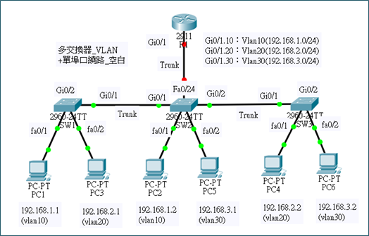
圖
8-13
單埠口多交換器繞路
路由器如路由器規劃如下:
|
Router |
Router port |
IP
位址 |
VLAN |
Switch port |
|
R1 |
Gi0/0 |
No address |
|
SW2(Fa0/24) => trunk Mode |
|
Gi0/0.10 |
192.168.1.254 |
dot1q 10 |
|
|
Gi0/0.20 |
192.168.2.254 |
dot1q 20 |
|
|
Gi0/0.30 |
192.168.3.254 |
dot1q 30 |
|
(B)
路由器設定
連接到交換器的埠口是
Gi0/0,須將它分割成三個子介面,再分別設定
IP 位址,如下:
|
R1#config ter
R1(config)#int gi0/1
R1(config-if)#no ip
address
R1(config-if)#int
gi0/1.10
R1(config-subif)#encapsulation
dot1q 10
R1(config-subif)#ip
address 192.168.1.254 255.255.255.0
R1(config-subif)#int
gi0/1.20
R1(config-subif)#encapsulation
dot1q 20
R1(config-subif)#ip
address 192.168.2.254 255.255.255.0
R1(config-subif)#int
gi0/1.30
R1(config-subif)#encapsulation
dot1q 30
R1(config-subif)#ip
address 192.168.3.254 255.255.255.0
R1(config-subif)#exit
R1(config)#int gi0/1
R1(config-if)#no
shutdown |
(C)
交換器設定
連接到交換器的埠口是
Fa0/24,須將它設定成
Trunk Mode,如下:
|
SW2>en
SW2#config
ter
SW2(config)#int fa0/24
SW2(config-if)#switchport mode trunk |
(D)
繞路測試:(請匯入:多交換器網路_VLAN
設定+單埠口繞路_完成.pkt)
█
PC1(192.168.1.1) ping PC3 (192.168.2.1)
[OK]
█
PC4(192.168.2.2) ping PC2 (192.168.1.2)
[OK]
|